
In this article, I would like to write about my recent experiment in constructing schmitt triggers using discrete components. I have constructed 2 versions and the latter version is employed in a flip-flop. This whole excercise is done just to see how they behave, and seeing transistors flip and flop is kind of amusing.
Classic 2-Transistor Astable Multivibrator
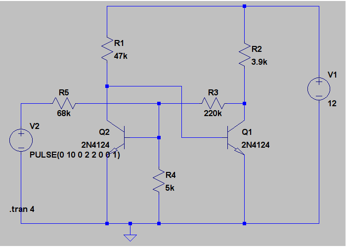
The classical 2-transistor astable multivibrator is the following circuit:

The drawback of this classic multivibrator is the weak rising edge of the resulting voltage. To me, I can see what kind of multivibrator is being used in some science displays in some museums in Jakarta. When I saw that the light blinks slowly, from total dark slowly to bright, I said to myself, “that’s weak”. Just a personal preference, really. In reality, the falling edge of the curve is not that sharp either. So no matter how you invert it or not, the resulting graph is weak rise/fall edges.
The other option is to use a digital schmitt trigger inverter, but it is not fun not to be able to see the individual components at work.
Transistor-Based Schmitt Trigger
Now enter schmitt trigger. The ones that I like the most are of the following designs:


Version 1A and 1B are basically the same design, except that one uses 2 NPN and the other uses NPN and PNP. The principle is the same, positive feedback weakened by a dividing resistor. Version 2 is kinda interesting, it is basically a very simple Op-Amp, with a feedback from the “inverting” output into the “inverting” input. Again, it is basically a positive feedback. The circuit employs 2 NPN transitors. Both designs are being tinkered using LTSpice IV. The component selections are done in such a way to meet my design criteria later.
Actually versions 1 and 2 are the variations that can be found on the web. There is another version, using 2 NPN transistors but I didn’t find it to my liking (although it may be the popular one to be used in an ASIC design).
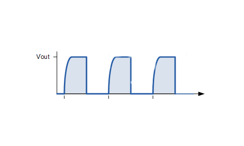
In general, the input/output characteristics are as follows:


As you can see from both simulation output, the resulting wave is a square wave. There is none of that ‘weak’ rising edge of the curve like that of the classic astable multivibrator. This is due to the fast switching behavior of the schmitt trigger; you either get on or off and the threshold changes depending on the state. The application of this schmitt trigger is limitless. I recall some hobby circuits for light/dark detection and turning on a lamp (at night, for example). Schmitt trigger will serve that purpose very well as it has the needed hysteresis.
The Resulting Circuit: LED Flasher
My objective is to create a LED flasher circuit with a very square wave output characteristic. Adding a capacitor/resistor as a timer into an inverting stage will result in the slow charging/discharging of the capacitor. The 1st circuit is as follows:
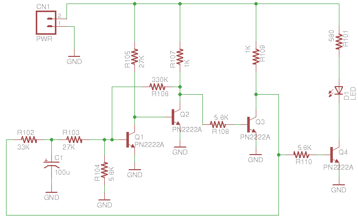
This circuit uses Q3 as an inverting stage, and you can see that the output is fed into a R102 and C1 to slowly charge/discharge it. It is then fed back into the schmitt switch. Q4 amplifies the state and drives D1 LED. The result is a sharp on and off state of the LED. It does take a lot of transistors in total, 4, but the result is a very amusing sharp on and off, none of that “that’s weak” multivibrator.
Another Circuit Version with Low Component Count
Another version that is the result of further tinkering, is a circuit based on the 2nd version of schmitt trigger. Remember that I noted that the component selection is based on my design objectives? The objective is add an amplifying stage, a PNP transistor, to switch on and off a LED. This requires certain voltage levels to be available to its base. That really is one of the design objectives.

This circuit is based on the schmitt trigger version 2. Q3 is a PNP that amplifies the output, it requires a low voltage of (Vcc – 0.7 V or less) to turn on and a high voltage of near Vcc to turn off. These voltage levels are the requirement for this design to work.
The end result is an astable multivibrator that has a good rising edge (as seen by the LED). Falling edge, on the other hand has that R6 bleeding C1 through R7 and the LED. This causes an interesting visual effect, in which the LED is turning off slightly like an incandescent lamp. There is that very subtle remnant of the brightness, weakening towards the end of the cycle, that is only visible on a high-brightness white LED. I think that is a nice visual effect to have. And in terms of component count, you can see that this design competes with the classic multivibrator, with only a couple of components more needed.


All in all, this has been a very educational experiment. I hope you will find it as amusing as I have found it. Thanks for reading.

Thanks for this. I’m trying to build a solar bicycle, and need reliable flashers for safety. My thinking is, the less components, the better, for reliability, so the 2-transistor astable multivibrator was my choice. I also didn’t want to entrust a critical safety system to a processor, because software can have bugs and hang.
LikeLike
Hi Roderick. I suppose if you want to keep the KISS principle, the simpler the better, if your application suits you.
Again, in my opinion, the schmitt is superior than the classical 2-transistor because as I said, it is not like, “it’s weak!”. Try it, I am sure you will be amused to see the transistors do all the hard work of jumping up and down abruptly instead of slacking off lazily of curving up and down….
LikeLike
Hi,
I chose the 1B circuit for an A/C control project. I needed a non-inverting ST to provide a negative-going pulse to trigger a 555 timer. The input is a rectified, slightly filtered, 5vdc with 2.5vpp riding above the 5v level. Normally, the input is “high” into the ST, which causes some heating of the NPN (2N3643), but otherwise works quite nicely. Thanks much for the 1B idea.
D.C.
LikeLike
Hi Doug, thanks for your comment. Did you do SPICE analysis of your circuit? Figure out your heating component, man. Time is your enemy; you want reliable product. Cheers.
LikeLike